Blinking LEDs with the ESP32 microcontroller
In the previous post we learned how to setup our Arduino IDE with the ESP32 microcontroller. In this blogpost we'll learn how to add some blinking LEDs.
What we'll need
Hardware setup
- Put your ESP32 microcontroller on a breadboard.
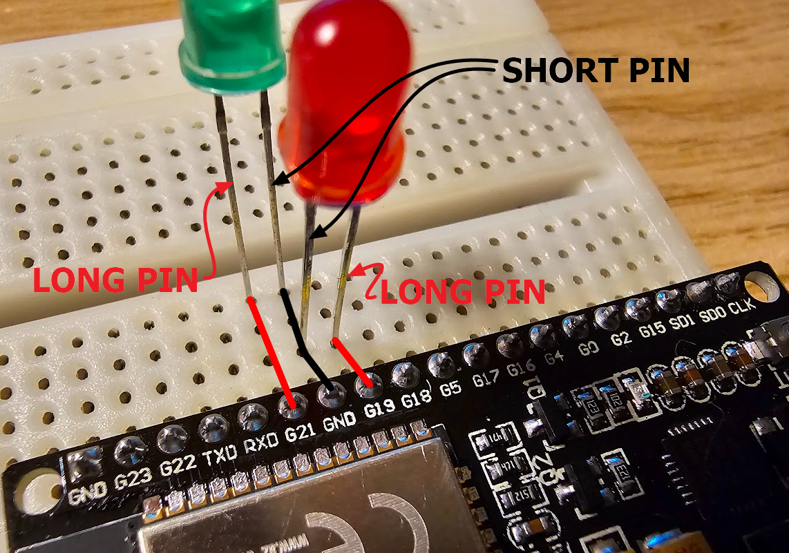
- Add an LED to your breadboard, but make sure that the shortest pin is connected to one of your GND pins of your ESP32 microcontroller. Connect the longest pin of the LED with the G19 pin of your ESP32 microcontroller.
- Add another LED to your breadboard with the shortest pin connected to the GND pin and the longest pin of the LED connected to the G21 pin of your ESP32 microcontroller.

- Summary:
- GND to short pin green LED
- GND to short pin red LED
- G19 to long pin red LED
- G21 to long pin green LED
Code for sketch
Create a new sketch in the Arduino IDE and add following code
int GREEN = 21;
int RED = 19;

void setup() {
  // put your setup code here, to run once:
  Serial.begin(9600);
  pinMode(GREEN, OUTPUT);
  pinMode(RED, OUTPUT);
}

void loop() {
  // put your main code here, to run repeatedly:
  digitalWrite(GREEN, HIGH);
  digitalWrite(RED, LOW);
  delay(500);
  digitalWrite(GREEN, LOW);
  digitalWrite(RED, HIGH);
  delay(500);
}
The provided code is an Arduino sketch that controls two LEDs (green and red) using the digitalWrite() function to turn them on and off in a pattern. Let's break down the code step by step:
1. Variable Declarations:
int GREEN = 21;
int RED = 19;
Two integer variables are declared to store the pin numbers to which the green and red LEDs are connected. These pin numbers correspond to the physical pins on the ESP32 board.
2. setup() Function:
void setup() {
  Serial.begin(9600);
  pinMode(GREEN, OUTPUT);
  pinMode(RED, OUTPUT);
}
In the setup function, initialization tasks are performed. It includes:
Initializing serial communication at a baud rate of 9600 bits per second, allowing you to communicate with the ESP32 through a connected computer via the Serial Monitor. Configuring the pins connected to the green and red LEDs as output pins using the pinMode() function. This tells the ESP32 that these pins will be used to control external devices (the LEDs) and not to read any input.
3. loop() Function:
void loop() {
  digitalWrite(GREEN, HIGH);
  digitalWrite(RED, LOW);
  delay(500);
  digitalWrite(GREEN, LOW);
  digitalWrite(RED, HIGH);
  delay(500);
}
The loop function is the core of the ESP32 program. It executes repeatedly after the setup function completes. Here's what it does:
digitalWrite(GREEN, HIGH);turns on the green LED by setting the voltage on the GREEN pin to HIGH (5V or logic level 1).digitalWrite(RED, LOW);turns off the red LED by setting the voltage on the RED pin to LOW (0V or logic level 0).delay(500);introduces a delay of 500 milliseconds (0.5 seconds), during which the green LED remains on and the red LED remains off.- The following two lines of code reverse the LED states: the green LED turns off and the red LED turns on.
Another delay(500);follows, maintaining this second state for half a second.
As a result, the code creates a simple alternating blinking pattern between the green and red LEDs, where each LED stays on for 500 milliseconds and then switches off for another 500 milliseconds in a continuous loop. This creates a visual blinking effect.
Compile and upload the sketch to the ESP32
Upload the code from the Arduino IDE to the ESP32 microcontroller by clicking the upload button.
Blinking LEDs!
Another adventure?
In this post we'll learn how to read temperature and humidity from a HDT22 sensor to our ESP32 microcontroller.
Want to know more?
See all my other posts about the ESP32 microcontroller.