Setting up Arduino IDE for ESP32 development
Embarking on the journey of working with the ESP32 microcontroller opens up a world of possibilities in the realm of electronics and embedded systems. To harness this potential, it's crucial to have your development environment seamlessly configured. This comprehensive guide will lead you through the process of setting up your Arduino Integrated Development Environment (IDE) to work harmoniously with the ESP32, laying the foundation for smooth and productive development. From installing essential components to creating and uploading your first sketch
Introduction
If you're diving into ESP32 microcontroller development, getting your Arduino Integrated Development Environment (IDE) properly configured is the first step. This guide will walk you through the setup process to ensure a smooth development experience.
Step 1: Install the Arduino IDE v2
If you haven't already, download the Arduino IDE v2 from the official source:
Once downloaded, launch the IDE.

Step 2: Add ESP32 Support to Arduino IDE
To work with the ESP32 board in the Arduino IDE, follow these steps:
- Open your Arduino IDE 2.0 and navigate to File > Preferences.

- In the Additional Boards Manager URLs field, paste the following URL and click OK:
https://raw.githubusercontent.com/espressif/arduino-esp32/gh-pages/package_esp32_index.json

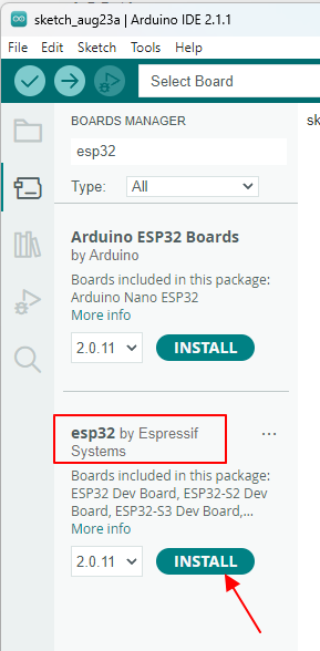
- Access the Boards Manager by going to Tools > Board > Boards Manager... or by clicking the Boards Manager icon on the toolbar.


- Search for ESP32 and install the esp32 package by Espressif Systems.

Step 3: Install Virtual COM Port (VCP) Drivers
To enable communication between your computer and the ESP32 board via USB, you'll need VCP drivers. Depending on your board, you might need different drivers, such as CP210x.
Install the drivers from these sources:
Step 4: Connect Arduino IDE to ESP32
Select your ESP32 board in the Arduino IDE:
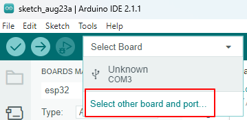
- Click the combobox in the Arduino IDE and choose Select other board and port....

- Choose your specific ESP32 board and the corresponding port, then click OK.

Step 5: Create a Simple Sketch
Let's write a basic sketch to test the setup:
void setup() {
  // put your setup code here, to run once:
  Serial.begin(9600);
}

void loop() {
  // put your main code here, to run repeatedly:
  Serial.println("Hello");
  delay(500);
}
This sketch initializes serial communication and sends "Hello" messages to the serial monitor at intervals.
Let's break down the code step by step:
void setup(): This is a special function in Arduino programming that is executed only once when the ESP32 board starts up. It is used for initializing and setting up any configurations or variables needed for the program.Serial.begin(9600);: This line initializes the serial communication between the ESP32 board and your computer. It sets the baud rate (data transfer speed) to 9600 bits per second. This is a common speed used for serial communication because it's a good balance between data transfer rate and reliability.
void loop(): This is another special function that runs repeatedly after thesetup()function has completed. Anything you place in this function will be executed over and over as long as the ESP32 is powered on.Serial.println("Hello");: This line sends the string "Hello" followed by a newline character (which moves the cursor to the next line) through the serial communication to your computer. This is used to display messages or data on your computer's serial monitor.delay(500);: This line introduces a pause of 500 milliseconds (half a second) in the program execution. During this delay, the ESP32 does nothing. This delay is used to control how often the "Hello" message is printed to the serial monitor.
In summary, the sketch sets up serial communication between the ESP32 and your computer at a baud rate of 9600. In the main loop, it repeatedly sends the string "Hello" to the computer's serial monitor every half a second (500 milliseconds). This creates a simple program where the ESP32 continuously outputs "Hello" messages with a short delay between each message.
Step 6: Compile and Upload
Compile and upload your sketch to the ESP32:
- Make sure your ESP32 is connected via USB.
- Click the upload button.

Observe the progress in the Output window. Something like this:

Step 7: Monitor Serial Output
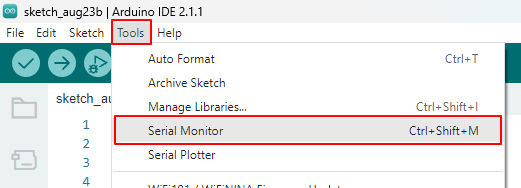
Open the Serial Monitor by clicking Tools > Serial Monitor.

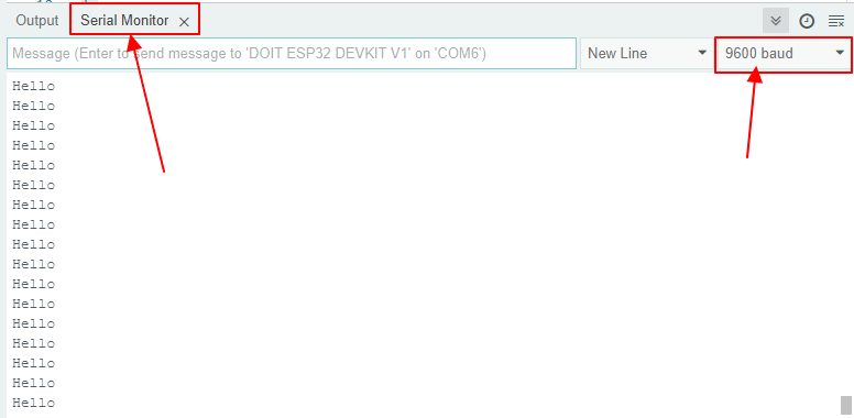
Now you should see all the Hello messages. If not make sure that you choose the 9600 baud in the combobox.

Conclusion
Congratulations! You've successfully configured your Arduino IDE for ESP32 development and deployed a simple sketch to your ESP32 microcontroller.
In the next post, we'll take a step further and learn how to control LED lights using the ESP32.
Want to know more?
See all my other posts about the ESP32 microcontroller.